
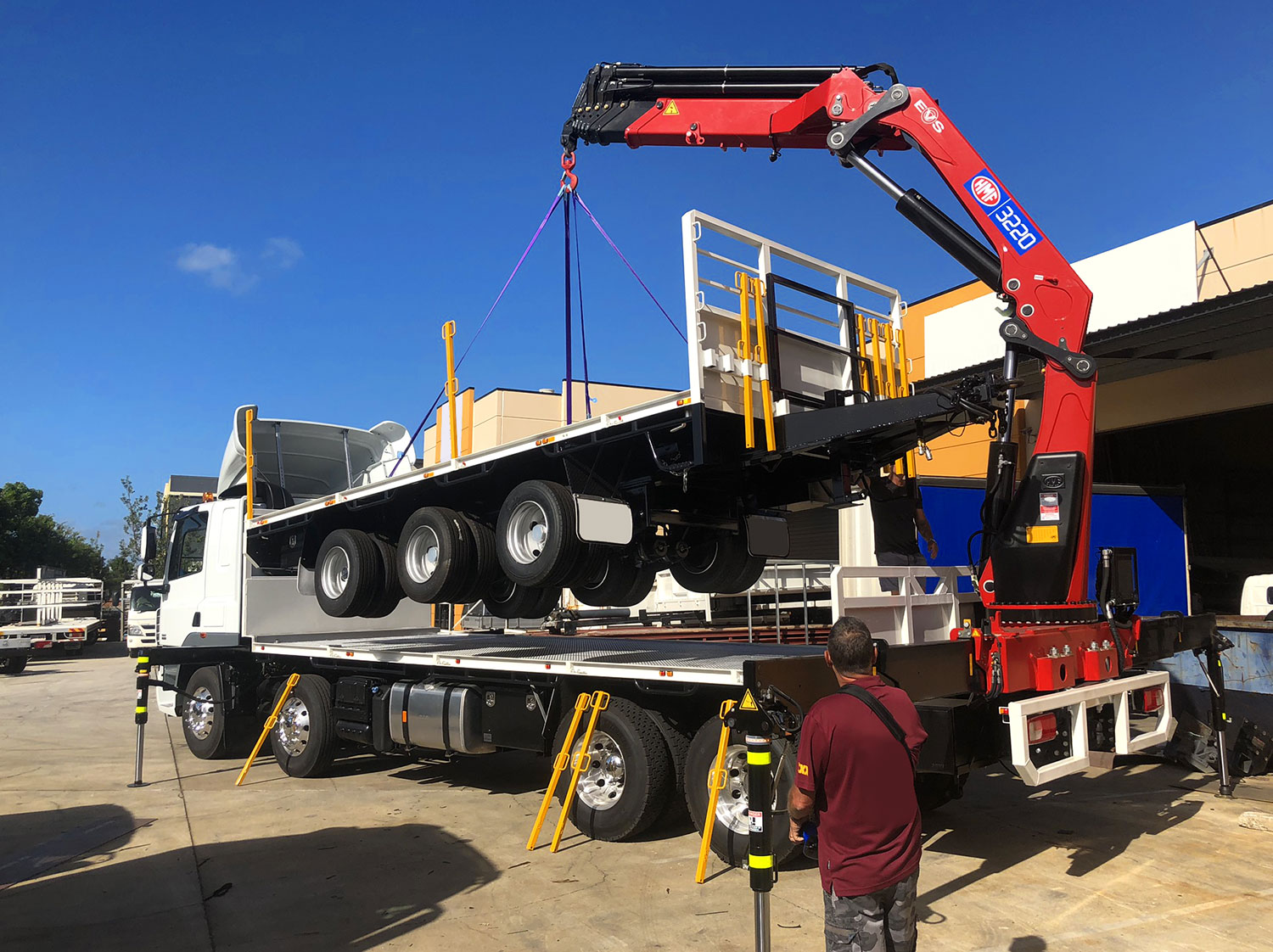
A vehicle-loading crane does not have a single fixed lifting capacity. The weight a crane can safely lift depends on how far the load is from the crane, how the boom is configured, which attachments are in use, and how the truck is set up on site. That variability is exactly what a crane load chart is designed to address, and understanding how to read one is fundamental to safe lift planning, crane selection, and day-to-day operation.
What Is a Truck-Mounted Crane Load Chart?
A crane load chart is the manufacturer’s rated capacity guide for a specific crane model. It shows the maximum weight that the crane can safely lift at different working radii and boom configurations, not a single number, but a matrix of values that change as the setup changes.
This is an important distinction from the tonne-metre rating you will often see in crane specifications. The tonne-metre figure is useful for shortlisting cranes and understanding where a model sits in the broader range, but it tells you nothing about what the crane can lift at a specific radius in a specific configuration; that is what the load chart is for. Every crane model has its own unique load chart, and the chart must match the exact crane configuration and any attachments in use. Using the wrong chart or applying figures from a similar model introduces serious operational risk.
Load Chart vs Tonne-Metre Rating
The tonne-metre class of a crane is calculated by multiplying the maximum load in tonnes by the distance in metres from the centre of the column at which that load is rated. It is a useful shorthand for comparing cranes and for understanding licensing requirements.
In Australia, crane operation requires a High Risk Work Licence (HRWL) once the crane’s rating reaches or exceeds 10 tonne-metres. But tonne-metre ratings describe a crane’s class, not its practical capacity in a given situation.
The load chart is where tonne-metre ratings give way to real-world numbers. A crane rated at 18 tm might lift close to its maximum near the column and a fraction of that at full boom extension. The chart shows both figures, and everything in between.
Why Maximum Capacity Can Be Misleading
The highest lifting capacity figure stated for a crane almost always applies at the shortest working radius, that is, with the load positioned close to the centre of the column. As the load moves farther out, capacity often decreases significantly. A crane that lifts 3,000 kg at two metres from the column centre might manage considerably less at eight metres with the boom fully extended.
This relationship between radius and capacity reflects the physics of load moment. The further a load sits from the crane’s column centre, the greater the rotational force acting on the structure. Crane load charts exist to make that relationship legible and to give operators a clear limit at every configuration.
The Main Parts of a Crane Load Chart
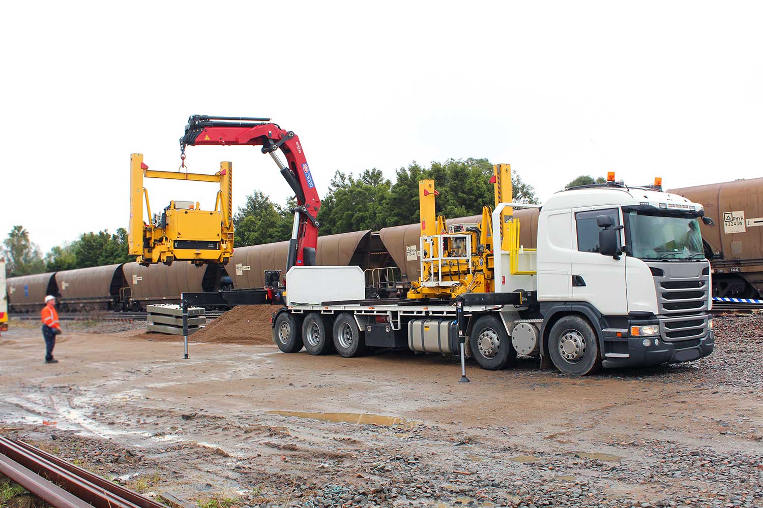
Crane load charts vary in format between manufacturers, but they share common elements. Understanding what each element represents is the foundation of reading them correctly.
Load Radius
The load radius is the horizontal distance from the centre of the column to the centre of gravity of the suspended load. This is not the diagonal length of the boom, and it is not measured from the edge of the truck.
As the boom angle changes or the boom extends, the horizontal distance to the load changes with it, which is why radius is used rather than boom length alone. If the required radius falls between two values listed on the chart, always use the lower capacity figure.
Boom Length or Hydraulic Reach
Boom length refers to how far the crane’s boom is extended. On a knuckle boom vehicle loading crane, this includes both the main boom sections and any fly-jib or extension in use. Extending the boom increases the working radius and reduces the available lifting capacity. Crane load charts typically show different columns or rows for different boom lengths, allowing operators to read the capacity for a specific extension at a specific radius.
Boom Angle
Boom angle affects the working radius. A steeper boom angle brings the load closer to the column centre, which generally increases available capacity. A shallower angle pushes the load further out and reduces it. Some load charts present capacity by radius alone, with boom angle implied, while others include an angle indicator column or require cross-referencing with a separate chart.
Rated Capacity
The rated capacity shown on a load chart is the maximum allowed lift weight under that specific configuration. It is not a suggested limit or an approximate figure; it is an absolute limit set by the crane manufacturer based on structural and stability testing.
Modern HMF vehicle loading cranes use a Rated Capacity Limiter (RCL), an onboard computer system that monitors the crane’s operating parameters and prevents operation beyond its rated capacity for the current configuration.
Gross Capacity and Net Capacity
Gross capacity is the maximum weight the crane can lift at a given radius and boom configuration, including the hook block, rigging, slings, and any attachments. Net capacity is what remains after those items are deducted, and it is the figure that applies to the actual load. Rigging weight is a common omission in lift planning, and on cranes operating near the top of their capacity at a given radius, that deduction matters.
How to Read a Truck-Mounted Crane Load Chart Step by Step
Reading crane load charts accurately requires a consistent process. Working through the same steps every time reduces the chance of errors and makes it easier to catch configuration issues before the lift begins.
Step 1: Confirm the Crane Configuration
Before anything else, the load chart in use needs to match the exact crane model and configuration. Any extensions, fly-jibs, winches, or grabs fitted to the crane affect available capacity and may require a separate chart or additional deductions.
Stabiliser position is part of that same check, as most crane load charts assume outriggers are fully deployed and that the crane is on firm, level ground. Uneven or sloped surfaces introduce stability risks that the base chart values alone do not account for.
Step 2: Find the Working Radius
Measure the horizontal distance from the centre of the column to the centre of gravity of the load. This is not the reach from the side of the truck, nor the diagonal boom length. Getting this measurement wrong is one of the most common errors in load chart use and consistently leads operators to underestimate the working radius and overestimate available capacity.
Step 3: Match Radius and Boom Length
With the working radius confirmed and the required boom length identified, locate the corresponding cell on the load chart. Most charts are laid out with load radius along one axis and boom length along the other, with capacity values in the intersecting cells. If the required radius or boom length falls between listed values, use the more conservative figure.
Step 4: Deduct Rigging and Attachments
The chart value is gross capacity. To find the net capacity available for the actual load, subtract the combined weight of the hook block, slings, shackles, and any other equipment attachments. If the total load weight, including packaging or any material still attached, exceeds the net capacity, the lift cannot proceed safely in that setup.
Step 5: Check the Notes Before You Lift
Crane load charts include notes, warnings, and operating restrictions that apply across the chart or to specific zones. These may include stability limitations at certain slew positions, restrictions when operating in particular directions relative to the truck, wind speed limits, or conditions in which capacity is further reduced. These notes are not optional reading; they are part of the chart.
Simple Load Chart Example
If you look at a straightforward lifting scenario, a crane operator needs to lift a piece of equipment weighing 1,500 kg. The load needs to be placed at a horizontal distance of six metres from the centre of the column, and the rigging, hook block and slings weigh 100 kg.
The total load to account for is 1,600 kg. For the lift to proceed, the crane load chart must show a gross capacity of more than 1,600 kg at six metres for the boom configuration in use.
| Item | Example |
| Load weight | 1,500 kg |
| Hook and rigging allowance | 100 kg |
| Total load to account for | 1,600 kg |
| Required radius | 6 m |
| Chart capacity needed | More than 1,600 kg |
If the chart shows only 1,400 kg at six metres for that boom length, the lift is not safe in that configuration. The operator’s options include repositioning the truck to reduce the working radius, shortening the boom, removing weight from the load where possible, or using a larger crane. If none of those is practical on-site, the right step is to stop and consult a competent person before proceeding.
What Affects Truck-Mounted Crane Capacity in Real Conditions?
The crane load chart provides rated values under controlled assumptions: firm, level ground, correct stabiliser deployment, no wind, and standard configuration. In practice, several factors can pull the actual safe capacity below those figures.
Load moment explains the most fundamental one. It is the product of the load weight and the horizontal distance from the centre of the column, and as the boom extends and that distance increases, the maximum allowable load must decrease to remain within the crane’s structural and stability limits.
Stabiliser setup and ground conditions carry similar weight. Charts assume outriggers are fully extended and correctly positioned on a surface capable of handling the loads through the pads. Short-legged stabilisers, sloped ground, or soft ground underfoot all change that picture. Subframe conditions are just as important for the same reason: they transfer loads between the crane and the truck chassis, and their integrity affects how those loads are distributed during operation.
Beyond those, several other variables affect what the crane can safely lift on a given day.
| Factor | How it affects capacity |
| Wind | Increases load swing and reduces safe lift weight |
| Load shape and centre of gravity | An unevenly distributed load behaves unpredictably once suspended and adds effective load on the crane |
| Dynamic forces | Slewing, extending, or lowering under load creates forces beyond the static chart values |
| Attachments | Fly-jibs, winches, and grabs add weight that must be deducted from gross capacity, and some require separate chart references |
Load Charts, Licensing and Australian Safety Considerations
In Australia, operating a vehicle loading crane at or above the 10 tonne-metre threshold requires a High Risk Work Licence (HRWL). The threshold is calculated as the product of the load in tonnes and the radius in metres. Requirements can vary between states and territories, so operators should confirm specific obligations with the relevant regulator. WorkSafe Queensland and Safe Work Australia both publish guidance on VLC licensing, competency, and safe operation.
A load chart is part of safe crane operation, but it is not a replacement for formal training, appropriate licensing, a site-specific lift plan, or compliance with the manufacturer’s operating manual. The relevant Australian Standards are AS 2550.11, which covers the safe use of vehicle loading cranes, and AS 1418.11, which addresses vehicle loading crane design. Both are referenced by state regulators and provide the technical foundation for safe crane operation requirements in Australia.
How Safety Systems Support Load Chart Use
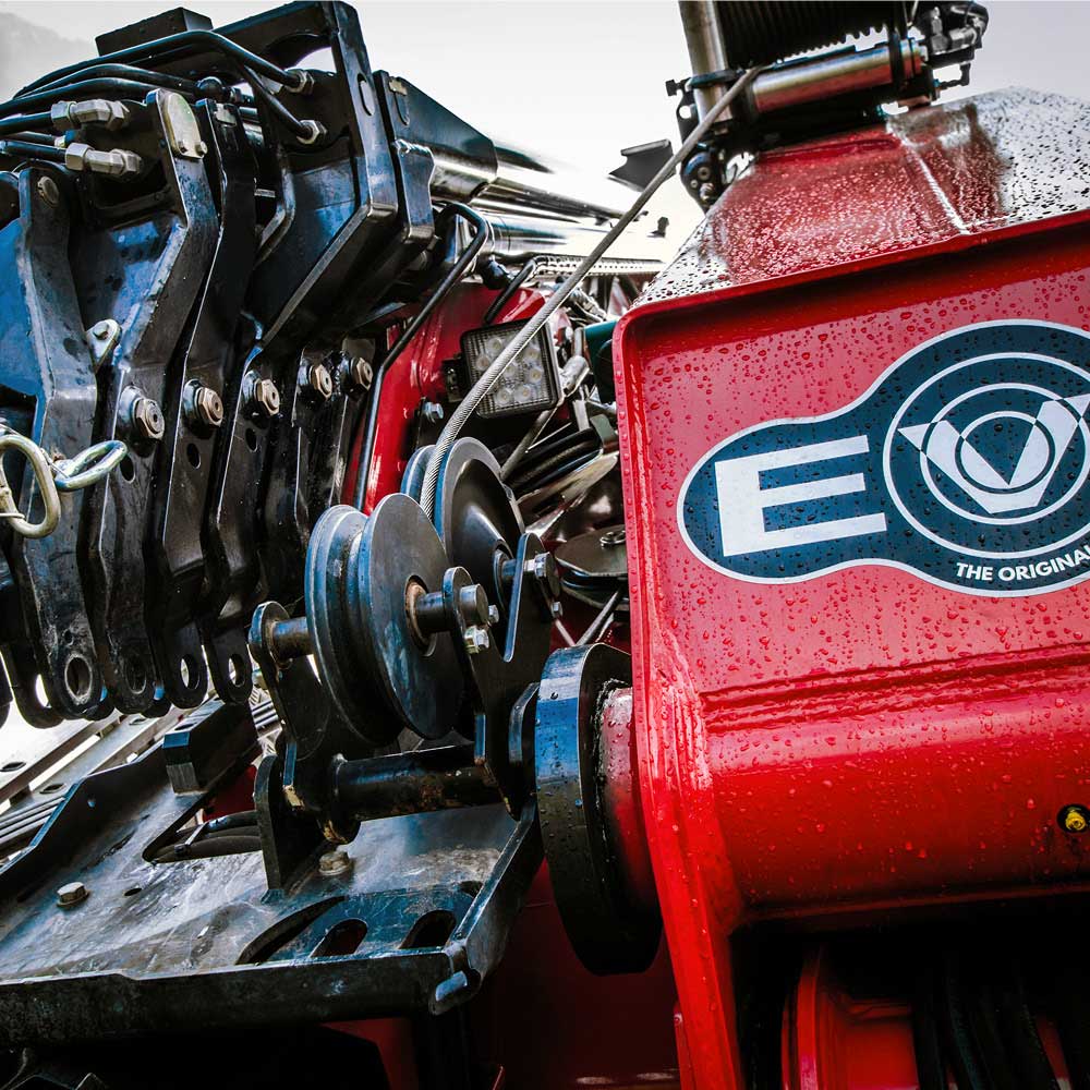
Modern vehicle loading cranes are equipped with safety systems that work alongside the load chart rather than replacing it.
The Rated Capacity Limiter fitted to HMF vehicle loading cranes is an onboard computer that monitors operating parameters continuously and prevents operation beyond the rated capacity for the current configuration.
HMF’s Electronic Vehicle Stability (EVS) system works alongside the RCL, using ongoing stability calculations to monitor the crane’s operating envelope and limit crane movement when the truck is on too great an angle. EVS is an optional upgrade rather than a standard feature across the range, and it is particularly relevant for larger crane configurations.
Both systems are backstops against errors, not substitutes for correct setup and chart interpretation. An operator who understands the load chart and plans the lift within the crane’s rated capacity is not relying on the RCL to catch an overload; they are working within limits the chart already defines.
Choosing the Right Truck-Mounted Crane Based on Your Load Chart Needs
Load chart knowledge is useful not just for crane operation but for crane selection. If you are comparing models or specifying a crane for a particular application, working through the load chart requirements before purchasing gives a more accurate picture of what you need than the tonne-metre rating alone.
Start by identifying the heaviest load you will regularly need to lift and the maximum working radius at which you need to lift it. Factor in the attachments you plan to use and their combined weight. Consider whether site conditions will affect the working radius or limit your setup options. If your requirements are likely to grow, building in some capacity margin makes more sense than specifying exactly to your current maximum.
HMF offers vehicle loading cranes across small (3–9 tm), medium (10–28 tm), and large (32–95 tm) capacity ranges. The tonne-metre class narrows the field; the load chart confirms the fit. The HMF Australia team can help match load, reach, payload, and operating requirements to the right model for your fleet.
Final Checklist Before Relying on a Load Chart
- Confirm the exact crane model and verify the chart matches it
- Confirm crane setup, including stabiliser position and deployment
- Identify the full load weight, including packaging or attached materials
- Measure the working radius from the centre of the column, not the truck edge
- Deduct the combined weight of rigging and attachments from gross capacity
- Check the chart notes for any restrictions on the planned configuration
- Assess ground and site conditions, including slope, surface stability, and outrigger spread
- Confirm the operator holds the appropriate licence and competency for the crane being used
- If there is any uncertainty about the lift, consult a competent person before proceeding
Need Help Choosing the Right Vehicle Loading Crane?
If you are comparing crane models or working through load and reach requirements for a specific application, HMF Australia’s team can help match the right crane to your fleet and jobsite needs. Explore HMF’s range of small, medium, and large vehicle loading cranes, or get in touch to discuss your lifting requirements directly.